
At the 2018 Ovation Users’ Group Conference, Emerson’s Sam Onuska and Greg Lieb presented improvements in advanced overspeed protection and online, real time testing of overspeed systems.
Greg opened describing where overspeed protection systems can be applied including steam turbines, gas turbines, boiler feed pump turbines (BFPTs) and hydro turbines. These systems measure the shaft rotational speed and decide & take action based on overspeed conditions by providing a method to reduce rotational velocity.
Here’s a view of a typical mechanical overspeed system:
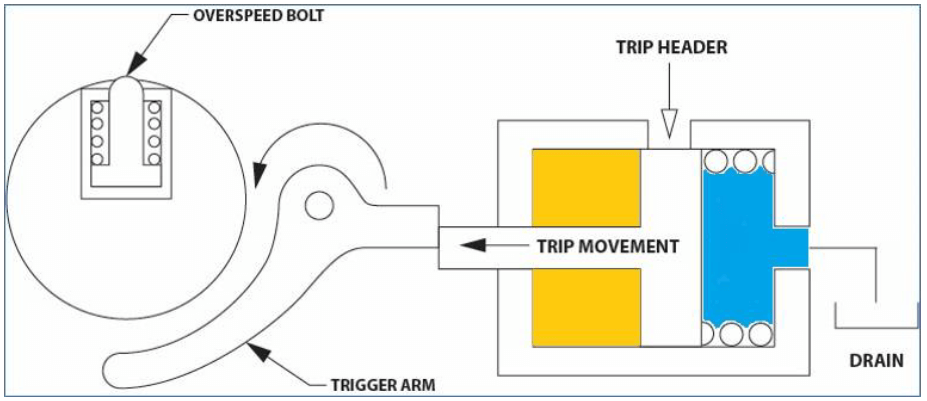
During an upgrade the trip lever and all associated linkages, hydraulic trip valve, pressure switches and tubing associated with the mechanical overspeed trip, reset and test are removed. Typically, the rotor-mounted equipment remains due to rotor balance considerations and costs versus benefits of removal.
Components of an Electronic Turbine Overspeed Protection system include speed probes—Eddy current, Hall-Effect, or variable reluctance probes. The decision and action steps are automated within the electrical overspeed protection system. In the decision step, a pulse train or sine wave is converted to rotational speed and compared with a speed setpoint. In the action step, if the setpoint is exceeded a relay’s state is changes and voted or non-voted outputs sent to initiate a trip.
An independent overspeed controller has redundant power supplies, 3 dedicated overspeed sensing channels, 3 digital output I/O for all other Ovation trips and testable dump manifold (TDM) testing.

Modes of testing include offline card overspeed testing, online card overspeed testing, testable dump manifold trip, and turbine manual trip.
General guidelines for electronic overspeed protection systems are detection prior to 110-112% rated speed with the setpoints specific to the turbine make and model. Per the API 670-Machinery Protection Systems standard, overspeed reaction time should less than 40msec. The response to the observed overspeed condition should limit the speed to less than 120% of the rated speed. This response is influenced by the module configuration, sampling rate and rotor acceleration.
The total system response consists of overspeed detection, trip signal to hydraulic system and hydraulic actuator / valve closure.
The advantages of electronic systems vs. mechanical systems include no moving parts, common set of spares, no loss of production during testing, turbine not placed in unsafe conditions, tunability of the system, improved live data and historical view and fault tolerance.


