Emerson’s Anand Iyer continues his series on Cloud I/O with his vision for what the future might hold for process automation systems.
Let us look at what effect the cloud IO concept would have on the distributed control system (DCS) as we know today:
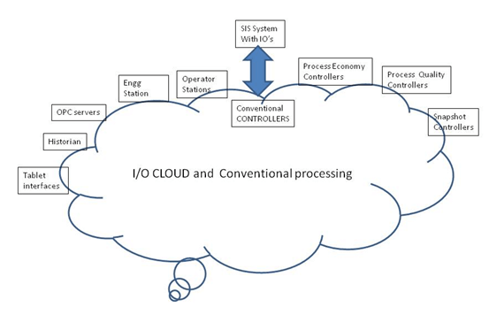
- The IO cloud forms the central part of the control system
- Conventional processing could be done in the IO cloud itself. For e.g. PID control being done in the IO as done in fieldbus systems such as Foundation fieldbus
- Conventional controllers may add to functionality sequences, equipment modules and additional modules could be done in conventional controllers
- OPC servers, engineering stations, operator stations, historians, OPC servers and other stations as per today’s control system could interact with the IO cloud
- Snapshot controllers could send snapshot information to the IO cloud
- Process economy controllers could run algorithms like multivariable controllers that run the processes economically
- Process quality controllers could run swap algorithms, statistical process controls (SPCs), and other advanced algorithms focused on getting required quality
- The SIS systems could provide information that may act as a secondary level of safety to process control systems
Constituents of the IO cloud
Non Control Input Bubble. The Process input IO bubble will generally have information about one input. The input conditioning could be done at the IO cloud itself i.e. the digital input (DI) or analog input (AI) soft module could be part of the IO bubble itself. Alarm processing could be done in the conventional controller or could also be a part of the IO bubble.
Note on snapshot interface: A steady-state snapshot will have various process values at certain values. For each steady-state snapshot, a process input will have a particular value. Similarly, different states will have different values of the snapshot.
Snapshot controllers could work in two ways, one method is where the snapshot comparison is done at the snapshot controller itself, and another way is where the snapshot values are stored in the IO bubble.
The Process Input analog bubble could have the following online information:
- Input value, engineering units
- Alarm states
- Snapshot states (for e.g. Steady state-1, Shutdown, Startup, Changeover A, etc.)
- Asset information
Configuration information. Transmitters could have information on:
- Analog processing
- Alarm processing
- Snapshot setpoints
- Other configuration information
Once we have some clarity on IO bubble, the next important thing that comes to mind is where is this bubble formed. The bubble could be formed in:
- A transmitter which has the analog input configuration block in it along with alarm setpoints
- An I/O card/channel which has the analog input configuration block, alarm setpoints, etc.
- A controller as in conventional systems
- There could also be a combination where some parts could come from the transmitter or I/O card and some from the controller.
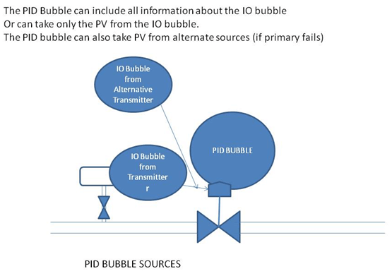
Process PID Bubble or Control Output bubble. Another type of bubble is the PID bubble. It may have a default process variable (PV), mode information, setpoint (SP), and output information.
Snapshot table in the field device could have different snapshots and their corresponding values.
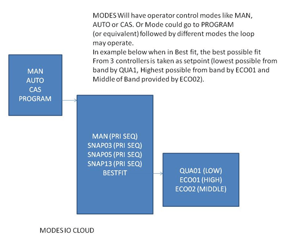
Modes will be more than the normal, Manual, Auto, Cascade, Cascade Snapshot 1 through n, Cascade economy 1 through n, cascade Quality1 through n.
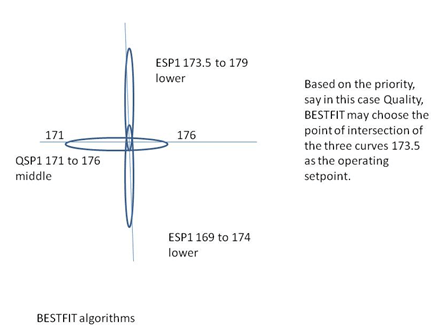
There could be interesting modes of operation. SP from economy controller could be to drive to lower temperature say 171 through 173, while quality could be to drive to higher 172 through 174. The priority for this loop could be economy and hence a SP of 172 could be chosen.
The PID bubble could have the following important parameters:
- Mode : Manual, Auto, Cascade, Program.
- Program could have many submodes: Manual (taken in manual by a program for a short duration), Cascade Snapshot 1….n, Cascade Economy 1…..n, Cascade quality 1…n, Remote Cascade, Remote Output.
- Mode Priority: This could be continuously changed by program logic or by operator. For example the priority order could be
- Sequential. Priority one above the other. Only one mode would be allowed. This could be true of Man and AUTO or Cascade.
- Once the Mode is changed to Program, Mode priority at this sub level could be Sequential selection of some modes (mostly temporary like a snapshot pulse of setpoints/ outputs or a program manual mode of a brief duration), And any such sequential selector would in the end put the controller in BESTFIT mode.
- BESTFIT would probably be the most optimized mode of operation
- Some Control loops may not have the BESTFIT option
- PV, SP, OUT, CAS_IN_PATH and other standard PID parameters could be the part of the PID bubble.
- The PID bubble can pick information from the main PV source or in select cases, from other alternate sources, were the primary source be not available for some reason (failure, maintenance and so on).
Digital Control Bubble. Devices like Motors, Valves could come in one Bubble. The Valve Feedback, Command to Valve could be in one bubble as in conventional devices.The DC bubble could have a mode and mode priority structure which is sequential. Being ON/OFF devices, bestfit algorithms may not be possible.
A SNAPSHOT could Change the state for a brief duration and then set back to the previous operating mode.
Digital Input Bubble. Digital information like valve close Limit switch on a manual valve or some operator selection or Reset buttons could probably be formed inside the Device itself.
Command Bubbles. Command bubbles come from different sources like the Operator station to set a valve output. This bubble will have information as to what valve is to be opened and who is opening it, what mode etc.
Snapshot Bubble. Let us take the example of a few elements of the reactor with 4 air lines, two feed lines and one out line. There are 4 Flow control Modules on the feed lines, one reactor pressure control valve (connected to vent), two feed flow control modules).
At the end of the startup of the reactor, the snapshot controller restores the steady state in one pulse lasting for 10 seconds. What it does is the following:
- FIC_AIR01 , Output Program Manual- 72%.
- FIC_AIR02 , Output Program Manual- 73%.
- FIC_AIR03 , Output Program Manual- 71%.
- FIC_AIR02 , Output Program Manual- 72%.
- FIC_FEED01 , Output Program Manual- 62%.
- FIC_FEED02 , Output Program Manual- 62%.
- PIC_REAC01, Output Program Manual – 63%
At the end of the 10 seconds, the respective control Modules are put in BESTFIT mode. (We assume here that the Quality and Economy controllers are up and running already). It is also possible that the SNAPSHOT BUBBLE feeds the last known good value to the Quality and Economy controllers too, so that everybody is in sync.
Where do these values come from? They are possibly a snapshot taken at some point of time by either the operator or by some auto algorithm informing of the best possible way of operation.
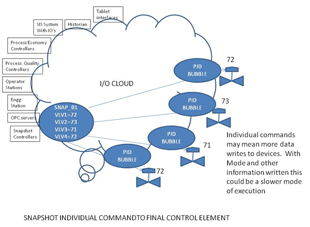
There are two ways in which the snapshot bubble can happen. One way is to have the SNAPSHOT Controller take control of individual device and write the values to all the control modules.
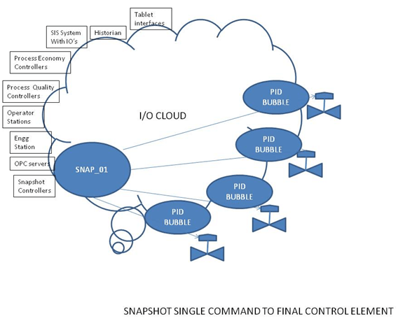
Another way is that the Snapshot controller sends a command SNAP_01 to the network and all the respective control Modules come to the last known good value and what actions to be taken by them in the SNAP_01 event.
Economy Processor Commands. Economic process operating controllers / algorithms could be a matrix based control system or multivariable controllers or some advanced control algorithm. The focus of the control Module is to have a best fit economic operation. Without worrying about the base algorithms we can say that in this example case, the economy processor may give commands to keep the setpoint in a range of say 134 to 136, preferring highest possible value.Now each process can have a variety of economic algorithms.
One set of control logic could be say due to the quality of raw materials. This will set up an economic model for operating the plant based on the chemical composition.
Another could be due to the state of the equipment. Or best optimum running of rotating equipment.
There could be a Multivariable controller trying to optimize the plant. And so on. Each of these could be in one processor or located in different processors/ workstations.
Each of these would give separate setpoint ranges to the control Module working at the base level. They would also give the direction to achieve the best economy for e.g., High (try to keep setpoint as high as possible in the range xx to yy), Low (try to keep Setpoint as low as possible in the range xx to yy) or Middle (try to keep setpoint between xx & yy).
The control Module would then operate in the BESTFIT mode. Take these different setpoints and get the best operating point.
Quality Processor Commands. Quality control algorithms could be simple swap algorithms as described previously, Statistical process control setpoints or other mechanisms used for maintaining the desired quality. A swap algorithm could give a required setpoint to a control module and try to achieve the most stringent quality needs. It could give setpoint in a range to the controller and the direction to achieve the best quality.Other quality algorithms could work with different processors and give setpoint ranges for operation and also the direction to achieve the desirable quality.