
Safety Instrumented Systems (SIS) in Plant Operations
Few would dispute the importance of Safety Instrumented Systems (SIS) in plant operations today. They are the vital last layer of prevention behind the control system – protecting the integrity of the plant, shutting it down in abnormal situations, and crucial to personnel safety, the environment and company reputation and finances.
SIS systems are the last layer of prevention that will hopefully ensure that disasters, such as Bhopal (1984), Texas City (2005) and Buncefield (2005) never happen again.
Yet how can we ensure we get it right when it comes to SIS and sensor selection? Let’s start with the SIS loop.
The SIS Loop
An SIS loop consists of a number of elements – logic solvers with multiple safety instrumented functions (SIF); final control elements; and sensors. It is the sensor – flow measurement devices, for example – that give the logic solver the necessary information to determine whether the SIF, designed to return the process to a safe state, should be activated.
Yet selecting the right sensors can often be a confusing and time-consuming process with numerous specifications to consider and decisions to make. Questions that must be addressed include:
- How can I effectively determine the risk reduction levels required and the safety integrity level (SIL) of my sensors?
- How can I design an SIS loop that meets the right SIL level and probability of failure on demand (PFD)?
- And how can I ensure SIS certification and adherence to international standards, such as IEC 61511?
Here’s an overview on how to navigate these challenges and ensure the correct sensors for your SIS needs. The result will be the long-term safety and sustainability of your plant.
Calculating Risk Reduction Levels
Every facility, every sector and every region is different. To this end, a hazard and operability (HAZOP) analysis is vital for identifying the likelihood of a specific event occurring and the necessary risk reduction requirements.
If the HAZOP determines the risk of an event occurring – a valve not closing, for example – is once every year and if the goal is once every 10,000 years, then your risk must be reduced by 10,000. How do we achieve this?
Identifying the Appropriate SIL Level and target Probability of Failure on Demand
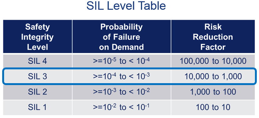
The main goal in designing an SIS loop is to meet the targeted safety integrity level (SIL) determined by the risk reduction factor (10 to 100: SIL 1; 100 to 1,000: SIL 2; and 1,000 to 10,000: SIL 3).
Yet, to fully understand the required sensors, the user must also understand PFD (Probability of Failure on Demand). PFD is the chance or risk that the sensor or SIS component will be in failure mode at the same time as when it is needed to bring the process to a safe state.
As each component has a PFD, the end user adds up the PFDs for all components in the overall SIF loop and can then compare against the IEC 61511 table. In the example illustrated in the figure below, the facility needed to reduce its risk by a factor of 10,000 – which corresponds to SIL 3. As can be seen in the same figure, the target PFD range is 10–4 to 10–3 meaning that the combined PFD of all SIF components must be less than 10–3 – – crucial information in determining sensor selection.
Navigating the Sensor Options – Certified or Prior Use
So, having identified SIL and PFD requirements, what are the options for choosing sensors?
There are essentially two choices. IEC 61511 specifies that a sensor may be safety certified if it is compliant with IEC 61508. This places the responsibility of safety certifying products on the manufacturer. The other choice is to select prior use sensors, where the end user must demonstrate that the sensor has been successfully used in a similar application with significant supporting documentation.
For IEC 61508 certification, two routes are available – firstly product design analysis based on failure modes, effects and diagnostics analysis (FMEDA) where the safe failure fraction (SFF) must be higher than 90% for SIL 2. The second option is for the sensors to have been field-proven based on a history of safe operations and a complete review of failure data. For the field-proven route, each component must have 100,000,000-unit operating hours, and the full device must have been operating in the field for a year or longer.
Today’s SIS Solutions and Applications
Having looked at some of the key issues around sensor selection, how are today’s providers meeting these requirements?
At Emerson, we adhere to IEC 61511 and 61508 standards (the accompanying IEC standard which covers the complete safety lifecycle) and the field-proven route to certification for our new SIS Vortex flow meters. With the capability of a quad configuration meter body, the Rosemount 8800 Vortex meter provides the industry’s first SIL certified Quad Vortex Flow Meter. With Systematic Capability up to SIL 3, it provides unmatched reliability and a simple drop-in safety measurement solution.
Rosemount Vortex meters are delivering safety in real-life applications today…
In a major refinery in Houston, steam measurement on crude oil heaters used DP flow configurations which suffered from unexpected failures due to impulse line plugging from heavy particulate oil. In this case, the existing DP flow meters were replaced with Quad SIS Vortex meters, with three out of the four meters run back to the logic solver and the fourth meter’s measurements fed back to the control system. The SIL IEC 61508 certification and the unique all casted and welded non-clogging meter body design gave the operator the confidence to switch.
Another example comes from an Indiana refinery and a light gas hydrating unit which encountered impulse lines plugging and clogging, due to the harsh Midwest winters. When these issues occurred, false readings and unexpected failures would trigger false trips to the logic solver. The deployment of Quad Vortex SIS meters eliminated the needs for impulse lines and complex and expensive heat tracing. The solution provided the best in reliability, safety and peace of mind.
Securing Peace of Mind in SIS Operations
SIS sensor selection is a complex process and must be done according to industry standards. Through a methodical approach to risk reduction, SIL target levels can be achieved with certified or prior use meters. With the development of new SIS flow meters – plant operators can ensure complete SIS compliance and the peace of mind they have long been waiting for.


