Update and bump: A LinkedIn post on this subject went viral, so I thought it would be worth sharing Riyaz Ali‘s thoughts on this subject again.
Abstract
Final Control Elements (Control valves or Safety Shut Down Valves) are the key components of any close loop control system, whether it is used for Basic Process Control Systems (BPCS) or for Safety Instrumented Systems (SIS). Financial constraints derive different constructions of valves suitable for throttling vs On-Off applications. However, due to past accidents, reliability has become a key criterion in the valve selection process. Many process industry manufacturers and producers, based on their plant-specific experiences, are tempted to use control valves in safety shutdown applications—specifically smaller-size valves, which may not be cost-prohibitive. This post will provide clarity on when to assign the SIL suitability for valves used in different scenarios (process control vs. safety shutdown) and establish criteria to assign SIL applicability for the “Final Element”.
Introduction
Safety integrity Level (SIL) is the discrete level for specifying the safety integrity requirements of the safety instrumented functions. It is a quantifiable measurement of risk used to establish safety performance targets of SIS systems. A SIL can be expressed in terms of Probability of Failure on Demand (PFD) or Risk Reduction Factor (RRF). Risk reduction factor is simply the reciprocal of PFD (1/PFD). SIL levels are designated in terms of PFD or RRF as a range of numbers.
PFD is a value that indicates the probability of a system failing to respond to a demand. PFD is a function of test interval time and failure rate of the equipment under control.
In short, to establish an SIL suitability rating for a Safety Instrumented Function (SIF) loop, a PFD value needs to be computed for the components of a loop. A SIF loop consists of a sensor, logic solver and final element. To calculate PFD, an equipment failure rate number is required.
Failure Mechanism
Failures are categorized so that failure data can be organized in a consistent way. ISA Technical report ISA-TR84.00.02-2002 – Part 1 talks about two failure modes – physical (random) failures and functional (systematic) failures.
Physical or random failures result from the degradation of one or more hardware mechanisms. It is often permanent and attributable to some component or module. For example, when a control valve is at the end of travel and not moving with the change in the control signal due to a broken shaft, the failure has occurred because of a physical failure of the component in the valve.
On the other hand, functional or systematic failures are failures related in a deterministic way to a certain cause, which can be eliminated by a modification of the design or manufacturing process, operational procedures, or other relevant factors. For example, a computer program has crashed and there is no physical damage, but the system has failed. The end result is that the program is not working, and a failure has occurred due to a systematic error in programming code.
A major distinguishing feature between a random failure and a systematic failure is that failures arising from a random failure can be predicted with reasonable accuracy, while systematic failures, by their very nature, cannot be accurately predicted.
With a basic understanding of failure mechanisms, it is clear that mechanical items like control valves, failures can be classified under the physical or random failure category, which is simpler by nature.
Systematic failures are typical characteristics of programmable electronic systems or microprocessor-based devices. The reliability concept has been around the industry for a long time but due to advancements in electronics and control systems, this concept is more crucial than ever before. Because a final control element is part of the control loop, its reliability data is also being questioned by end-users.
This leads to a basic question:
Does a “final control element” require a SIL suitability rating?
To understand the exact need, let us discuss control systems used in process sector industries. Control systems are frequently separated into two categories: systems that protect the equipment, classified as “Safety Instrumented System” and systems that control the equipment, known as “Basic Process Control System.” Final control elements are part of both systems.
According to IEC 61511 part 1, 3.2.3, Basic Process Control System has been defined as:
Basic Process Control System (BPCS)
A system which responds to input signals from the process, its associated equipment, other programmable systems and/or an operator and generates output signals causing the process and its associated equipment to operate in the desired manner but which does not perform any safety instrumented functions with a claimed SIL ≥ 1.
This definition leads us to conclude that a BPCS is any system that has a SIL<1. Therefore, SIS systems employing Safety Instrumented Functions with a specified safety integrity level, which is necessary to achieve safety function, need to have a SIL rating equal to or above 1.
This above conclusion raises some interesting questions:
1. Why are control valves to be SIL certified?
Industry practices and routines generally define which valve design need to be used for a safety versus control applications. However, due to reliability attributes of control valves, especially on smaller sizes, make them suitable for safety applications.
Financial considerations and maintenance aspects (using same valve design for both control and safety) are making control valves attractive for safety applications. We can categorize in three different scenarios as below, where control valves can be used as safety shut down valves.
CASE 1: Control valves which are used only as an on/off single final element
CASE 2: Control valves which are used in a dual-purpose context (both for control and safety)
CASE 3: Control valves which are used in a dual-purpose context in addition (redundancy) to an on/off valve
Illustration for Case 1
A control valve is used for safety applications. In this case the control valve is a “Final Element” of a SIF Loop and needs to have SIL rating equal to or above 1.
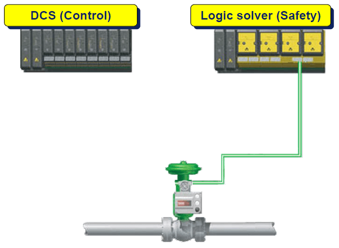
Case 1
Illustration for Case 2
Is it possible to use single control valve common for both safety and control?
According to IEC 61511 part 1 clause 11.2.10, it states that a device used to perform part of a safety instrumented function shall not be used for basic process control purposes, where a failure of that device results in a failure of the basic process control function which causes a demand on the safety instrumented function, unless an analysis has been carried out to confirm that overall risk is acceptable.
This may possibly lead to following interpretation.
- YES: If all possible failures of the control valve do not place a demand on any SIF than control valve may be used with no further analysis. In this case, the control valve is the “Final Element” of SIF loop, and it needs to have a SIL rating equal to or above 1.
- NO: If failure of the control valve will place a demand on a SIF, then it may not be used as the only final element in that SIF.
- If failure of the control valve will not place a demand on SIF, for which it is intended but may place demand on any other associated SIF than the control valve may be used in a SIF only after detailed analysis. An additional step for further analysis will be necessary in these cases to ensure that the dangerous failure rate of the shared equipment is sufficiently low. In this case, the control valve is a “Final Element” of the SIF loop, and it needs to have SIL rating equal to or above 1.
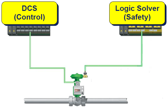
Case 2
Illustration for Case 3
In this scenario, a control valve is used to provide additional hardware fault tolerance for a higher SIL application, which is like using a control valve for safety but with the added burden of justifying and verifying the SIF design and its final SIL value.
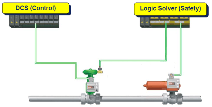
Case 3
2. Why are control valves that are used in a BPCS required to be SIL certified?
As per IEC definition, a SIL rating is not required but it is possible that reliability data for a valve may be required. Industry or end user may require failure rate data of equipment or in loose terms, MTBF (Mean Time Between Failure).
Essentially MTTF (mean time to fail) is the right term to define product reliability. It is usually furnished in units of hours. This is more common for electronic components, but trends are seen even for mechanical items.
3. How can MTTF provide useful data for the calculation of PFDAVG (probability of failure upon demand)?
MTTF can be simplified to 1/(sum of all failure rates) or equal to 1/λ. In general, components of MTTF can be categorized in the following categories:
Safe Detected (λSD)
Safe Undetected (λSU)
Dangerous Detected (λDD)
Dangerous Undetected (λDU)
This data leads to useful information:
- MTTFs (Mean time to Fail Safe)
- MTTFd (Mean time to fail Dangerous)
- SFF (Safe Failure Fraction)
MTTFs can be computed by adding λSD and λSU and reversing the number. MTTFd can be computed by taking λDU and reversing the number.
SFF can be computed using the equation = 1 – (λDU) / (λSD + λSU + λDD + λDU) or (λSD + λSU + λDD) / (λSD + λSU + λDD + λDU).
PFDAVG can be calculated using simplified equation of failure rate of equipment under control (EUC) times test interval divided by two.
MTTFs calculations provide plant availability, which is a very important measurement of process plant up-time capability. A spurious trip that is considered a safe but unplanned trip may be too strenuous for piping and other equipment. Not only are production and quality affected, but profits may also be as well. Also, it is important to consider the higher risk associated with plant start up. IEC 61508 stresses more on “safety event”, in case of demands, which relates to dangerous undetected failures and are used to compute PFDavg.
As such, mechanical equipment like valve bodies and actuators do not have any diagnostics capabilities. According to IEC 61508 part 2, table 2, with a hardware fault tolerance (HFT) of zero, they can only be used in SIL 1 applications. A digital valve controller mounted on a “Final Control Element” improves the diagnostic coverage factor, which in turn improves the SFF number, allowing the possible use of higher SIL rated applications (Per IEC 61508 part 2, table 3) by use of the Partial Stroke Test.
Conclusion
If control valve is designated to carry out a safety function, then it should meet the SIL level of the Safety Instrumented System Function loop. In this case, failure rate numbers will be required to compute the total PFDavg of the loop. The end user may possibly ask for third party certification to comply with IEC 61508 requirements to meet certain SIL suitability.
However, if a control valve is designated for normal process control than as per IEC61511-3 part 1, section 3.2.3, Basic Process Control System, definition does not designate control valves to have SIL suitability.
References
i) International Electrotechnical Commission, “Functional Safety – Safety instrumented systems for the process industry sector” – IEC61511
ii) International Electrotechnical Commission, “Functional Safety of Electrical / Electronic / Programmable Electronic Safety-Related Systems” – IEC61508
iii) Control Systems Safety Evaluation & Reliability – William M Goble
iv) ISA Technical report ISA-TR84.00.02-2002 – Part 1