Last year around this time, the fourth edition of API Standard 682 – Pumps—Shaft Sealing Systems for Centrifugal and Rotary Pumps was released. This standard:
…specifies requirements and gives recommendations for sealing systems for centrifugal and rotary pumps used in the petroleum, natural gas, and chemical industries.
This standard has evolved alongside technology advancements since it was first introduced in 1994 and adopted as the global standard, ISO 21049. The fourth edition indicates a preference for continuous measurements using pressure and level transmitters instead of switches to monitor pump auxiliary seal flush systems—especially for pumps used in hazardous, flammable and/or toxic services.
 A new whitepaper, Beyond Switches for Pump Monitoring: What Changed with API Standard 682 highlights ways to interpret this data from the transmitters to help minimize failures and reduce pump maintenance costs and process downtime.
The whitepaper’s authors explore the costs of pump failures and typical mean-time-between-failure (MTBF) data that can vary from less than two years to more than ten years for top-quartile performers.
API 682 defines piping plans for selection and installation of pump auxiliary seal flush system sensors and controls. The whitepaper goes into the most common plans 52, 53A, 53B and 53C.
Plan 52:
…uses an external reservoir for providing buffer fluid between the seals of an unpressurized dual seal system. Dual mechanical seals are used where the pumped product is harmful or hazardous and process fluid leakage to the atmosphere should be minimized and contained.
Plan 53A:
…consists of dual mechanical seals with a barrier liquid between the seals. The barrier liquid is contained in a pressurized reservoir. There will always be some small leakage flow of barrier liquid into the product. The system uses an external source of pressure, typically nitrogen, to keep the reservoir pressure sufficiently higher than the pump seal chamber pressure.
Plan 53B:
…consists of an external barrier fluid system pressurized by a bladder accumulator that supplies clean flush liquid to the seal chamber. The accumulator and barrier liquid are maintained at a pressure sufficiently higher than the seal chamber.
Plan 53C:
…uses a piston accumulator instead of a bladder to provide pressurized barrier fluid to the circulation system. The piston accumulator senses pressure from a reference source, normally a line connected to the seal chamber, and generates a higher pressure using an internal spring to protect the seals.
Here’s a view of how the various piping plans are instrumented:
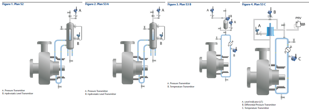
Click to enlarge
Request your copy of the whitepaper for descriptions of each plan and recommendations for guided wave radar level measurement, automation and the use of wireless transmitters.
You can also connect and interact with other measurement and reliability experts in the Pressure, Temperature, Level and Reliability & Maintenance groups in the Emerson Exchange 365 community.