We’ve discussed the topic of compressor surge control numerous times here on the blog. The posts continue to be some of the most popular ones.
I received a note from the now-retired Roman Bershader, who has vast experience in anti-surge control. He is a retired engineer and now a consultant with a bachelor’s and a master’s degree in aerodynamics and a Ph.D. in experimental fluid dynamics.
His patent, Methodology and algorithms for protecting centrifugal and axial compressors from surge and choke, was awarded in 2022. He explained that his paper was a tribute to Naum Staroselsky and two of his numerous patents, Control system for controlling a dynamic compressor and Method and apparatus for preventing surge in a dynamic compressor.
Roman shared that the thrust of Naum’s ideas:
…was always to place the surge limit line (and by analogy the choke limit line) in a universal orthogonal coordinate system, where the movement of the operating point along the performance curve is determined by the angle of rotation of a line drawn from the center of the coordinate system, and then transform this two-dimensional space into a one-dimensional control variable for the PID controller.
Roman described how his algorithm works and how it’s best suited for protecting dynamic compressors. I wanted to share it to continue the education process around this important control challenge.
A universal orthogonal coordinate system can be described as a system in which the surge and choke lines are constant, hence independent of compressor speed, suction conditions, and gas molecular weight, and in which the region of stable operation is strictly separated from the regions of instability. Such a system can only be defined by applying Buckingham’s π-theorem with recalculation of the various dimensionless variables characterizing compressor operation. As a result of extensive field testing of all types and sizes of dynamic compressors and analysis of the collected data, it was concluded that such dimensionless π-coordinates are: the ratio of pressures in the compressor Rc and the Mach number Ma – a fundamental dimensionless quantity in gas mechanics – at the inlet or outlet of the compressor, depending on the location of the flow meter.
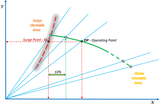
The signal from a differential pressure flow meter of any type, which is so common in industrial applications, divided by the static pressure signal at the same location, is a quantity proportional to the square of the Mach number. Therefore, the universal orthogonal coordinate system can be represented in FIG. 1 by replacing the Y coordinate by the pressure ratio Rc and the X coordinate by the differential pressure signal divided by the static pressure signal (∆P/P).
FIG. 1 – Sketch of a common compressor performance curve
For the relatively flat performance curve shown in FIG. 1, where the surge limit line is recalculated from the compressor performance maps provided by the manufacturer, only two points are available to the compressor control system: the operating point OP itself and the point on the surge limit line SL having the operating point pressure ratio Rc. The positions of both points are determined by projections onto orthogonal axes.
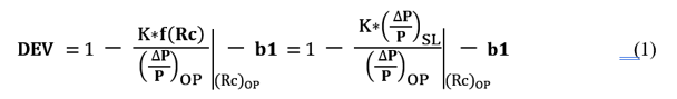
The equation below was chosen to transform the universal two-dimensional space of FIG. 1 into a one-dimensional control variable DEV for the PID controller:
Where: DEV is the control variable; K is a constant/scale parameter used for surge testing; f(Rc) is a pressure ratio function representing the surge limit line; (∆P/P)SL is the surge point on the surge line at given pressure ratio of the operating point; b1 is the desired safety margin.
The recommended standard safety margin for industrial compressors is 10% of the surge line as the minimum flow rate to ensure stable compressor operation.
As shown in FIG. 1, the 10% safety margin is measured and calculated from the projection of the SL point on the surge line onto the horizontal axis. If the performance curve is relatively flat, the 10% safety margin is a smaller portion of the projection of the entire performance curve. But this is not the case for the relatively steep performance curves typical of axial or high-pressure ratio centrifugal compressors, as shown in FIG. 2.
FIG. 2 – Sketch of a steep compressor performance curve
The choice of the desired safety margin b1 in equation (1) must somehow reflect the slope of the performance curve to correspond to a safety threshold of 10% of the minimum flow rate. That is, the choice of the optimal b1 is a kind of analytical process of working with compressor maps, which becomes more complicated in the absence of maps.
This deficiency can be substantially corrected if the universal orthogonal coordinate system shown in FIG. 1 and FIG. 2 is replaced by a modified coordinate system in which the main parameters are angles rather than projections, and where the slope of the compressor performance curve plays no role.
In such a coordinate system shown in FIG.3, the horizontal axis will be the Mach number Ma of the operating point, calculated as Const – √(∆P/P), and the vertical axis will be the Mach number as a function of the pressure ratio Ma(Rc), determining the Mach number of the surge point at each given pressure ratio Rc.
FIG. 3 – Image of the movement of the operating point in the form of the ray rotation angle
In the modified coordinate system, the surge line becomes a beam with a constant angle of 45 degrees, measured from the vertical axis, since at each point of such a line MaOP = Masurge.
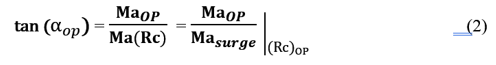
The angle αop between the vertical axis and the beam passing through the operating point determines the angular displacement of the operating point relative to the surge line in the compressor’s stable operating zone, regardless of the direction of movement, since the surge limit zone is determined by a constant angle of 45 degrees. The value of the tangent of the operating point angle αop is calculated as:
Then the process variable for the PID controller, which can be expressed as a percentage of the angle αop, can be calculated using the formula:
After this, the desired safety threshold of 10% can be set in the same way as for any PID controller, simply by setting the SP setpoint = 10%.
Returning to equation (1), which has been used so successfully for many years, it should be noted that the equation contains a component of the angular characteristic of the displacement of the operating point 1/(tan²(αop)), unlike the parameter b1, which has the meaning of a projection on the horizontal axis and depends on the slope of the performance curve:
Conclusion
The most accurate compressor protection method is the one based on the angular variable represented by equation (3), which describes the movements of the operating point with high accuracy regardless of direction, and linearly with respect to changes in both compression ratio and flow rate, which facilitates the tuning of the anti-surge PID controller.
In the absence of compressor maps, relatively not difficult compressor field tests can be performed to determine the surge limit line for the PID controller configuration and then simply set the required safety threshold as a setpoint .
Taking into account the piping layout, check valves, silencers, intercoolers, separators, and the response time and size of the anti-surge valves, the required safety threshold should be as low as possible to protect the compressor and ensure maximum operating efficiency by minimizing unnecessary gas recirculation or air bleed. This can be achieved by series testing during commissioning. The resulting value, for example 10%, can also be considered as a diagnostic parameter indicating deterioration in compressor performance or failure of system components if 10% is no longer protective over time.
The angular coordinate method allows to simplify the multi-level operation of the compressor to a one-dimensional visualization of the safe operating zone, presenting it as a direct comparison of the process variable with the set value, which is the most common and convenient practice for plant operators monitoring processes in the DCS.
Both dimensionless π-coordinates Rc and Ma are scales that uniformly define the operating range for all compressors. Therefore, in such coordinates, it is possible to track the position of surge lines and the rotation of performance curves with increasing pressure ratio and compare different compressors at the design stage, optimizing the compressor selection.


Fisher anti-surge valves with digital valve controllers coupled with highly accurate Rosemount measurement transmitters are important elements in effective PID control using this algorithm.