
Excitation systems run quietly for years, and then one morning the unit will not build voltage. At a recent Ovation Users’ Group session, Matt Pizarchik, Excitation Engineer at Emerson, covered how voltage regulators work regardless of manufacturer, the most common failure modes in the field, and the diagnostics built into Ovation excitation controls.
Why It Matters
 Your excitation system does not make megawatts, but you cannot run the plant without it. It sets your generator’s reactive power position and holds terminal voltage steady against a grid constantly pushed around by other equipment on the same bus. When a unit drops out of automatic control, it loses its limiters, its protective features, and its compliance position at once. Most of these problems are visible well before they become outages.
Key Takeaways
- Automatic voltage regulator (AVR) and excitation system all mean the same thing, and the job is identical across manufacturers.
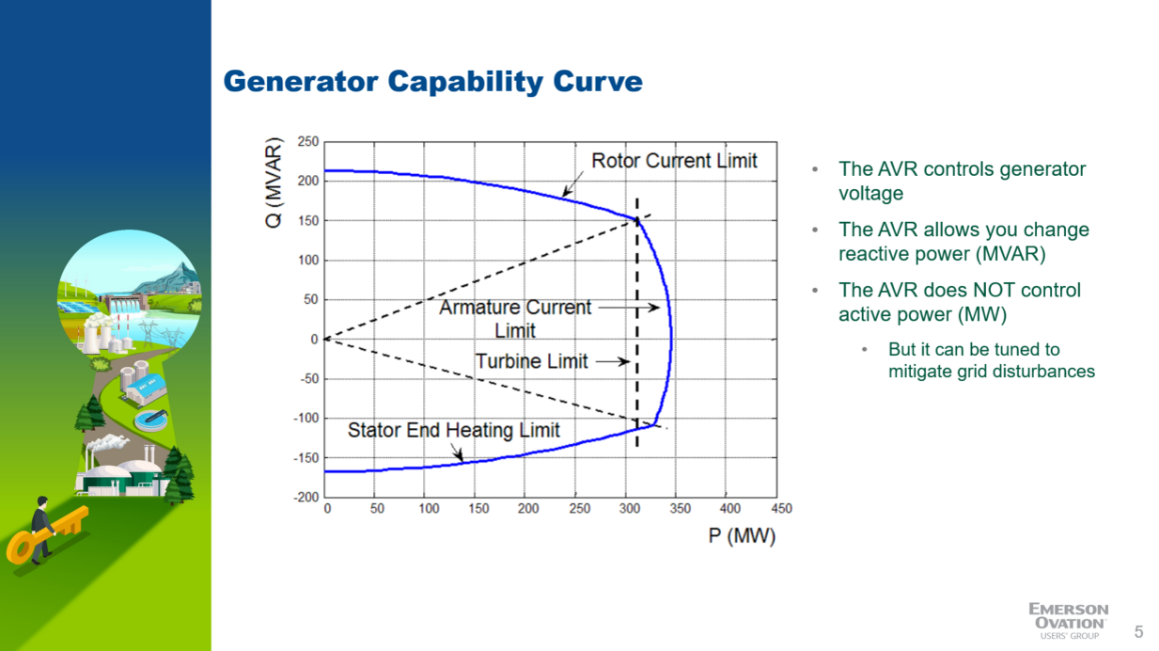
- Excitation moves the unit along the reactive axis of the capability curve; turbine torque moves it along the megawatt axis.
- Rising field current over time to maintain the same generator voltage is the clearest early warning of a developing problem.
- Ground faults on the field windings are always real, and often trace back to the power potential transformer.
- The Ovation Excitation System controls capture data at 390 microseconds, the resolution compliance reporting requires.
What the Excitation System Actually Does
An excitation control system is, stripped of terminology, an elaborate alternating current-to-direct-current converter. The input is always three-phase, from the generator bus or a permanent magnet generator on the turbine. Thyristors, also called SCRs (silicon-controlled rectifiers), rectify that waveform into a choppy direct current output that energizes the generator field. Generators do not mind the choppiness. The field windings become a large electromagnet, and the current through them sets terminal voltage.
From there it behaves like any other loop in the plant. The regulator compares terminal voltage against a set point and rectifies more or less input to close the gap. Raise excitation and voltage rises, putting the unit in the lagging region of the capability curve. Lower it, and the unit moves into negative MegaVARs (MVAr), the leading region.
Outputs span 20 amps to 10,000 amps. A static exciter feeds the field windings directly and needs thousands of amps to reach rated voltage. A rotating, or brushless, exciter is smaller because an intermediate stage on the rotor rectifies and passes current to the field, at the cost of more equipment on the machine.
Why Automatic Control Is the Only Mode You Want
While the unit is online, the excitation system must be operated in automatic voltage control, and that is where the power system stabilizer, limiters, and protective features live. If a potential transformer fuse blows or the sensing signal degrades, the regulator transfers to manual and holds field current constant instead of voltage.
That is not a place to sit. Regulatory bodies expect automatic voltage control, so extended time in manual usually means a shutdown is coming. Volts-per-hertz protection is also unavailable, since the regulator cannot see the voltage it would protect. And because the bus moves on its own, a unit holding constant field current can wander outside its capability curve, bounded by rotor current above and stator heating below.
The Failures That Show Up Most Often
Excitation problems share symptoms, so Matt framed them as a checklist rather than a diagnosis.
- Total loss of generator volts. Check other protective relays and any second set of potential transformers to see whether the loss is plant-wide or local to the AVR. Confirm 120 volts at the knife switch inputs, look for blown fuses, and verify the interface modules.
- No regulator output. Confirm power at the excitation source, station service, or a self-excited feed. Check the field-flashing supply and contactor, the gate-pulse cards that switch the thyristors, and the field connections, sometimes left off after an outage.
- Rising field current. If it takes more field current to reach the same voltage, something is degrading, often diodes or fuses in a rotating exciter. That data goes to the historian, so you can trend field current at load and no load across years and see the slope.
- Ground faults. Every system ships with ground fault detection on the generator field, the exciter field, or both. A reading in the kilo ohm range warrants taking the system down and checking resistance throughout, including upstream into the bridges and the power potential transformer.
Two more: auto synchronizer pulses too narrow to move the set point, and phase rotation rolled at the regulator input after an outage.
Tools Built for Compliance and Root Cause
The digital excitation control module is the brain of the system. An Ovation excitation system arrives as a new drop with two OCR3000 controllers and two redundant, plug-and-play excitation control modules that pass control back and forth, running at 390 microseconds against a 10 to 50 millisecond controller scan.
Two capabilities depend on that speed. The Excitation Software Toolkit pulls high-resolution data from the modules to an engineering laptop for export to your compliance group or to Emerson. High-speed event capture records 30 seconds before and after any trigger, defaults to every shutdown, and supports custom triggers written in Developer Studio.
Those files open in the standard Ovation Trends application under an events option, available on Ovation 3.6 or later. That is the resolution MOD 26 re-verification calls for: the 2 percent step test required every five years and re-triggered whenever you change the excitation system or rewind the generator.
Because the system is another Ovation drop, operators use the same graphics, historian, and alarm logs, with standard Ovation modules for spares. Emerson supports full replacement, built and tested in Pittsburgh, or a digital front end on existing bridges, plus three-day on-site training.
Planning an excitation upgrade, or want more from the diagnostics already in your system? Explore the Ovation Automation Platform on Emerson.com.