Sometimes when you read an article about tuning proportional-integral-derivative (PID) loops, you’re treated to all the 2nd order differential equations they contain. These can be intimidating, especially if your college calculus classes are many years in the rearview mirror.
 If you find yourself in this situation, there’s a great Chemical Engineering Progress article, Implement an Effective Loop Tuning Strategy, by Emerson’s Tim Olsen and Norman Ito. They provide a really good overview of PID control as well as easy-to-understand tuning guidelines to help you improve the performance of your production process. These guidelines are broken down into 8 steps.
They open the article noting that much of PID loop tuning today is done by feel. The loops are typically tuned as fast as possible without creating oscillations. They note:
However, by tuning only individual loops, the overall process performance and the ability to recover from disturbances are reduced. When a process has been tuned by feel, console operators often need to put controllers in manual operation to settle the process down after a major process disturbance.
They provide good descriptions of the proportional, integral, and derivative terms and how these terms impact bringing the process variable (PV) back to setpoint (SP) and the various forms of the PID algorithm—series (classical), standard (ideal or ISA), and parallel. We highlighted the first two in an earlier post, Getting the Converted PID Values Right. The parallel form is not often applied in process control applications.
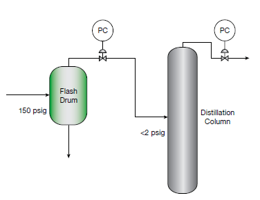
 Step 1 in the process of loop tuning is to understand the process and operating objectives. They cite an example of “effectively controlling a distillation column to obtain the desired product quality and yield.” Some of the loops should be tuned more aggressively than others to achieve this objective:
…the distillation column’s pressure controller should be more aggressively tuned than the flash drum’s.
Step 2 is to prioritize the control loops into fast and slow execution. This is especially important for interacting loops. If priorities are equal then the loops will fight each other and not reach a stable state. In the distillation column example, Tim and Norm note:
…maintaining the flash drum at 150psig is not critical to the separation. The flash drum can be used as a variability buffer to absorb disturbances from the reactors. Lowering the priority of the drum pressure control loop minimizes disturbances to the distillation column.
At the risk of too many steps in one sentence, step 3 is to perform step testing. This is done by placing the controller in manual mode and changing the output by a small percentage—0.25%, 0.5%, or 1% depending on the sensitivity of the process. It should be large enough not to be lost in the noise and not large enough to cause serious disturbances to the process. They caution:
…make sure that you understand the process and the expected changes to prevent unwanted process upsets. For example, when performing a step test in a refinery, do not reduce the hydrogen quench flow because this will cause a temporary runaway in the hydrocracker reactor; start by increasing the hydrogen flow, and then reduce it back to the standard rate.
The type of valve will have an impact on the process gain (%flow/%output). Step tests will determine the process dynamics of the loop as well as help identify problems such as sticky control valves.
Step 4 is to resolve the hardware issues found in the step-testing phase. This leads into step 5, to repeat these step tests of loops that had hardware fixes. Steady state gain is the difference in the PV before and after the step test divided by the output change. The time constant, tau (Ƭ) is the time required to reach 63.2% of the final process change. Deadtime (Td) is the amount of time after the change in output is made that the process begins to respond.
These values take you to step 6, calculate tuning parameters. The tuning examples shared in the article are based on Lambda tuning:
Lambda tuning refers to all tuning methods in which the control loop speed of response can be selected as a tuning parameter; the closed loop time constant is referred to as lambda (λ).
They recommend starting the tuning with a lambda that is 3x the greater of tau or deadtime. Several examples are provided including self-regulating processes and ratio control.
Step 7 is to input the new PID tuning parameters and observe how they perform. The final step, step 8, is to follow up on the loop tuning as needed to ensure desired performance. It would be great if things never changed, but they constantly do.
I think you’ll find the article very approachable and filled with examples to help sharpen your PID tuning skills.
| iTunes


