Large-scale solar and wind energy projects play a key role in meeting the global demand for renewable energy, but effective energy storage solutions are needed to provide consistent electricity during cloudy or dark hours, and during windless periods.
Hydrogen electrolyzers are one such solution, converting excess energy into hydrogen (H2) for storage, transport, and eventual use. Our article in the June 2025 issue of H2Tech, titled “Control valve selection for H2 electrolyzer applications,” provides an overview of the electrolysis process used by electrolyzers, and it highlights specific control valve considerations for this application.
Electrolysis explained
Electrolysis is a fundamentally simple process that uses electricity to separate water into H2 and oxygen. The major components of an electrolyzer include the electrolysis cell—which consists of a cathode, an anode and a semi-permeable membrane—and some type of electrolyte. Direct current (DC) drives the cell and generates oxygen on the anode and H2 on the cathode. In a typical electrolyzer, multiple cells are combined to create a stack.
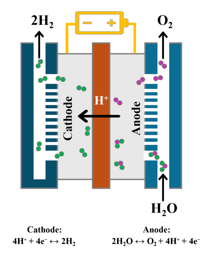
Figure 1. Electrolysis uses DC power to separate water into H2 and oxygen. The process is reversable, so H2 can be stored and used to create emission-free electricity during high energy demand.
The electrolysis process can be reversed to convert stored H2 back into electricity.
There are several major types of electrolyzer technologies in use today, but we will focus here on proton exchange membrane (PEM) electrolyzers because they provide several major advantages: faster startups and turndowns, a modular design for easier scalability, and high-pressure H2 delivery without the need for an expensive downstream compression system.
The PEM process
With PEM electrolyzers, ultrapure water (UPW) is pumped into the anode, where DC power splits water molecules into oxygen, free electrons, and H+ ions. The H+ ions then pass through a semipermeable perfluorinated acid ionomer membrane and pick up electrons to form H2 molecules. After H2 leaves the electrolyzer, it undergoes dehydration and deoxygenation treatments to reach final purity.
Key control valves in this process can generally be divided into UPW, H2, and oxygen categories.
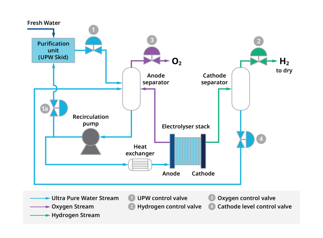
Figure 2. UPW is pumped into a PEM anode cell (upper left) and creates oxygen. H2 is formed in the cathode cell (lower right) as H2 ions move through the membrane and pick up electrons. The pressurized H2 is dehydrated and sent to storage.
UPW control
Valves in the first group regulate UPW flow to the electrolyzer and back to the water purification unit. These valves encounter highly variable flows and pressure drops during startup, shutdown, and operation. Globe valves with the appropriate trim are usually a good choice, providing a wide control range. Material selection is also important because UPW can dissolve metals under certain conditions.
H2 control
The H2 control valves maintain backpressure on the cathode separator. During startup, the pressure drop across the valve will be very high, but once in production, the valve should maintain minimal pressure drop to increase efficiency.
Globe valves are effective here as well, but in some cases a configuration of multiple valves may be needed. Careful valve design and material selection are essential because H2 can cause embrittlement in some metals. In addition, H2 is very flammable, so low-emission packing and robust flange connections between the valve and pipeline are a must.
Oxygen control
The oxygen valve bleeds oxygen off the anode separator and maintains proper backpressure on that vessel.
Once again, valve design and material selection are crucial because high-concentration oxygen can be a fire hazard. Rigorous cleaning and shipping procedures are also required to eliminate any traces of oil or contamination that could cause a fire or explosion. These valves typically vent to atmosphere, taking a full pressure drop, so a low noise trim is usually required.
Cathode level control
The cathode level control valve belongs to the UPW valve group, controlling the water level in the cathode separator. In addition to typical UPW concerns, this valve must also handle H2 outgassing.
Final valve selection factors
The best valve body style can vary based on specific operating parameters, so end users should seek a full understanding of startup, shutdown, and operating conditions. Incoming power consistency should also be considered because rapid fluctuations can create significant process dynamics that require quick and accurate valve positioning. Ultimately, end users are encouraged to leverage the knowledge of an experienced valve partner to address any questions and concerns.
Learn more about hydrogen electrolysis production here and download a brochure for hydrogen-ready control valves.