At the request of a reader who commented on the last post, here is another of the 11 examples that Emerson’s Mark Coughran shared in his Emerson Exchange Denver presentation, Solving Pressure Control Loop Problems in Hydrocarbon Processing Plants.
The commenter wrote:
Could you please write up a post about Acid Gas Removal Unit, Absorber Pressure and Flow? I’ve done some process safety assessment on acid gas/ H2S removal unit based on thermal oxidizer and would like to know your take on absorber based solution.
Here is the process diagram Mark described:
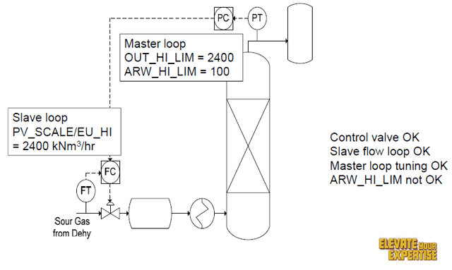
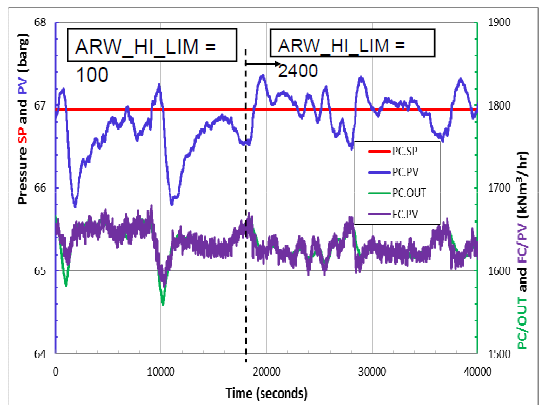
As found, the cascaded PID pressure and flow loop anti-reset windup setting was doubling the swings in the absorber unit pressure and flow from the dehydration beds. Once the setting was changed from 100 to 2400, the pressure and flow swings were significantly attenuated, as you can see in this trend plot:

Anti-reset windup (ARW) protection is a standard feature of industrial PID controllers. In some DCS, ARW limits are adjustable besides output limits. The ARW limits may not be at their best values. ARW default values may not match up with output limits as output scale and engineering units change. While we normally think of the ARW limits being set equal to the output limits, this has not been the case before the advent of the digital positioner and is not the case when external reset feedback or an enhanced PID is used. Here we take a closer look at the past and future use of anti-reset windup options and smarter reset action.
He shares some key considerations:
First and most important, if you have adjustable ARW limits make sure the range of the ARW limits is consistent with the range of the output limits. When output scales are set different from 0-100% due to engineering units in the output or operating limits, the ARW limits may not automatically change, remaining at the default of 0-100%. For cascade control loops, the primary PID output may be in the engineering units of the secondary loop depending upon the vintage and type. Also, the primary output limits may be set to match the setpoint limits of the secondary PID.
Greg also notes:
In some DCS if the ARW limits are inside the output limits, integral action is 16 times faster when the output departs from the output limit than when the output approaches the output limit. For the temperature loop example, the ARW high limit being at 100 and the output limit at 200 causes the integral action to be 16 times faster when the primary temperature PID output is decreasing between 100 and 200. In this case, the high reset action promoted undershoot and cycling.
The question is should the ARW be set inside, equal to, or outside the output limits? The answer depends upon the application and the DCS implementation of the integral mode.
Finally, he shares some examples and points to a 2012 Emerson Exchange presentation for more on ARW:
If your DCS has the positive feedback implementation of integral mode and consequently the external reset feedback option as shown in slide 15 in the Emerson 2012 Exchange presentation “Effective Use of PID Features for Control and Optimization“, you have a more effective method with no adjustment. If you turn on external-reset feedback (e.g. dynamic reset limit), and have the external reset signal correctly configured, you inherently have anti-reset windup. In this case, the ARW limits should be set outside of the output limits to get the effect of the ARW out of the picture. Your output will come off of the output limit when the proportional contribution to the output becomes less than the integral contribution with the total contribution inside the output limits. To make the output come off of the output limit sooner you can either increase the reset time or increase the controller gain. The more conservative choice is to increase the reset time since this increases stability. Most process loops on vessels and columns have too much reset action and would benefit from a larger reset time anyway.
You can connect and interact with other variability and process optimization experts in the Operate & Maintain group in the Emerson Exchange 365 community.