Microwaves have many uses including communications, navigation, radar, radio astronomy, heating and power, and spectroscopy to name a few. For instrumentation and automation, radar level measurement works by emitting microwaves to measure distance. The first radar level measurement system was installed on a commercial oil tanker in 1976.

The whitepaper describes the radar frequencies used for level measurement and the advantages and disadvantages of the various frequencies. Like most things in engineering, there are tradeoffs with the various frequency ranges used for non-contacting radars. Microwave frequencies used in these applications include:
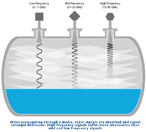
…low microwave frequency (C and X-band, 6–11 GHz), mid frequency (K-band, 24–29 GHz) and high frequency (W-band, 75–85 GHz).
As the frequency increases so does the attenuation (reduction) of the signal. The whitepaper uses the analogy of music where you are more likely to hear the bass than the treble from your neighbor playing loud music, since the higher frequencies attenuate more before reaching you and don’t travel as well through walls and other obstacles.
In non-contacting radar level measurement applications this means that:
…high frequency radars are more likely to have problems with condensation, vapor, foam, build-up on the antenna, and dust. Low and mid frequency signals with wavelengths in the range of 50 mm to 10 mm are less affected by these kinds of challenges and more likely to pass through them unaffected.
The antenna that receives back the reflected microwave signal is also affected by the frequency.
The beam angle and beam width is determined by the antenna design in combination with the microwave frequency. High frequency signals can achieve small beam angles with small antennas. Equally, small beam angles can be achieved with low frequency radars, but this requires larger antennas.
The size of the beam has advantages and disadvantages. An advantage of a small beam angle is:
…that it can make it easier to avoid hitting installations in the tank.
A disadvantage is:
…if there is an obstruction directly below the radar a narrow beam will be completely blocked, but a radar with a wider beam will be only partially blocked and still able to measure the product level.
Higher frequencies are more sensitive to antenna misalignment or turbulence on the surface of the liquid being measured which may scatter and disperse the signal and miss being picked up by the antenna.
Microwaves remain unaffected by surface irregularities such as turbulence if the wavelength is larger than the ripple size. For example, the signal return of high frequency radars will be affected and scattered by ripples down to 3,8 mm (0.15-in.) in size, whereas mid-range frequencies will remain unaffected by turbulence up to 2.5 times as large and be reflected as if from a flat surface.
Here is a table of the strengths and weaknesses of the radar frequencies for various level measurement applications:
|
Low Frequency: 6-11 Ghz |
Mid frequency: 24-29 Ghz |
High frequency: 75-85 Ghz |
|
|
Strengths |
|
|
|
|
Weaknesses |
|
|
|
Read the whitepaper for more about application suitability for dirty and contaminating applications, tanks with condensation and/or vapor, applications with turbulence, waves and ripples, applications with foam, and vessel sizes, and solids level measurement.
If you’re going the October 24-28 Emerson Exchange conference here in Austin, make sure to catch the Level Applications & Selection Considerations Meet the Experts session to discuss the right level measurement technology for your application. You can also connect and interact with other level measurement experts in the Level group of the Emerson Exchange 365 community.