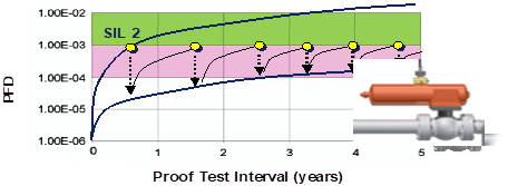
 I received a question from a very old post here on the blog, Credit for Partial Stroke Tests in Verification Process. The person was trying to get a better understanding about this chart showing how partial stroke tests (PSTs) can extend the intervals between full stroke tests for final elements in a safety instrumented function (SIF).
I turned to Emerson’s Riyaz Ali for help with this question. Riyaz explained that PSTs can only uncover partial undetected dangerous failures of mechanical valve integrity. They provide limited diagnostics coverage during these partial stroke tests.
Riyaz noted that the global safety standards IEC 61508 and IEC 61511 are generally prospective in nature. Diagnostic coverage factors (DCF), are defined in standards but do not provide a prescriptive way to estimate the number applied in real process applications.
Diagnostic coverage (DC) as defined in IEC 61511 is ratio of the detected failure rate to the total failure rate of the component or subsystem as detected by diagnostic tests. DC does not include any faults detected by proof tests.
For safety applications the diagnostic coverage is typically applied to the safe and dangerous failures of a component or subsystem. For example, the diagnostic coverage for the dangerous failures of a component or subsystem is DC = λDD / λDT, where λDD is the dangerous detected failure rate and λDT is the total dangerous failure rate (Dangerous Detected and Dangerous Undetected). Depending upon the DCF, partial stroke testing enables the extension of the full-stroke testing interval to X number of years while still maintaining the same probability of failure on demand (PFD).
Here’s a typical example of the math behind the extension of the full-stroke test interval from one to three years, using simplified equation from ISA-TR84.00.02-2002 – Part 2 (1oo1).
Case 1: For a full stroke test assuming DC is 100% and the proof test one year (no partial stroke test).
PFDavg = [(DC)(λd)(TI/2)] = (1)(λd)(1/2) = 0.5(λd)
Case 2: Adding partial stroke testing assuming a DC of 70% for the partial stroke with test frequency of four times per year and full stroke proof test interval of 3 years.
PFDavg = [(DC)(λd)(TI/2)]p + [(1-DC)(λd)(TI/2)]F = [(0.7)(λd)(0.25/2)] + [(1-0.7)(λd)(3/2)] = 0.09(λd) + 0.45(λd) = 0.54(λd)
The diagnostic coverage factor is a function of applications, process fluid, physical properties of fluid, operation history, maintenance records, environmental conditions, test philosophy, etc. A complete valve assembly needs to be considered to find the failure mode effect and diagnostic analysis (FMEDA) to help determine type of failures, which can be established by a partial stroke test.
If the valve is fully open during normal operation, then partial stroke tests will not examine for a tight shut off. For a fully open valve during normal operation when the process fluid is such that it starts coagulating or polymerizing at the valve seat, partial stroke tests will not detect it. The type of service, dirty or clean, will also affect the DCF. If fluid is flammable or toxic and tight shut off is a must, then the DCF by partial stroke will go quite low.
Riyaz shared that as a manufacturer, Emerson Automation Solutions will restrict the DC factor to a maximum of 70%, but depending upon the application specifics, it can go lower.
For final elements equipped with the Fisher FIELDVUE DVC6200 digital valve controller, partial stroke tests can possibly detect:
- Shaft/stem misalignment
- Packing fraction
- Leak in pneumatic system (pressurized path including tubing, fittings, actuators, etc.)
- Leak in supply pressure
- Plug – cage galling (asymmetric travel)
- Linkage connections between shaft and digital valve controller
- Shaft bearing wear out/torque requirement
- Connection between actuator shaft and plug shaft
- Broken spring or permanent set of spring
From these diagnostics, a suitable FMEDA report can be prepared for individual applications. It can provide a better guide for selecting proper DC numbers for comparison of the numbers that are based on mechanical components or theoretical generic numbers.
Visit the Digital Valve Controllers and Partial Stroke Testing sections on Emerson.com to learn more about how these diagnostic tests can extend the interval between full stroke tests as part of your safety lifecycle proof tests.